Electric Exhaust Brake Installation & Operating Instructions
Watch on YouTube instead.
Our brake was invented to be simple, affordable & reliable for every truck owner on the planet!
Select the instructions you want to view...
Installation Instructions
Exhaust brake will not function properly without being calibrated to your vehicle.
SEE INSTRUCTION STEP #16 BELOW.
Verify the Included Items
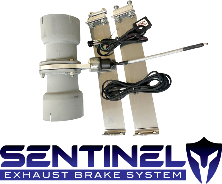
Sentinel Exhaust Brake System™ Assembly
(1) BM2000 Main Harness with Control Box
(1) Secondary Jumper Harness
(1) Switch
(2) Band Clamps
Zip Ties
Wire Connectors
Shrink Tube
PosiTap
Safety Information
Park vehicle on level ground and set parking brake.
Allow exhaust system to cool before beginning work.
Disconnect negative battery cable(s).
Use protective eyewear and gloves.
Required Tools & Supplies
Tape measure
Marker or scribe
Sawzall or exhaust pipe cutter
Grinder or file
Welder or heavy-duty exhaust clamps
Drill with 13/16" (20 mm) bit
Wire strippers and crimpers
Electrical tape & zip ties
9/16" End Wrench
9/16" Socket & Ratchet
Exhaust Brake Installation
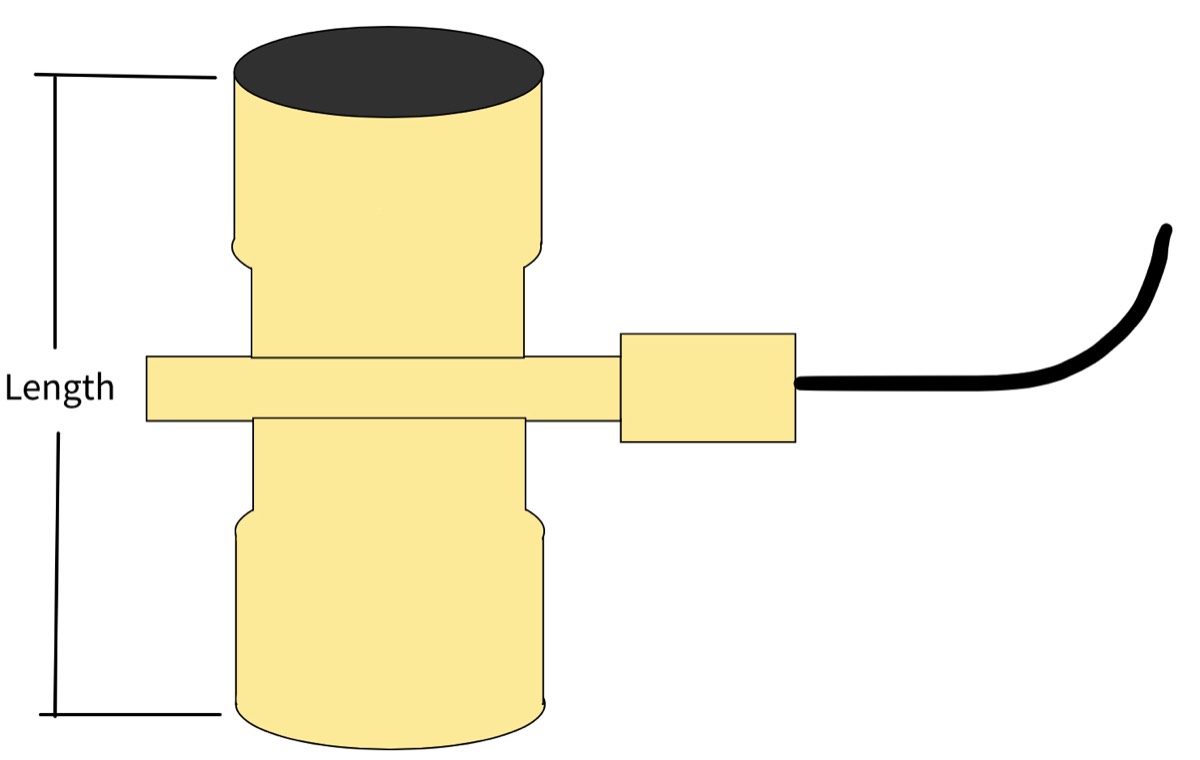
Measure the overall length of your Sentinel Exhaust Brake and subtract 4" (2" on each end) to get the measurement you will cut out of your exhaust pipe. (E.g., If the Sentinel Exhaust brake is 11" in length you will cut out 7" out of your exhaust pipe.)
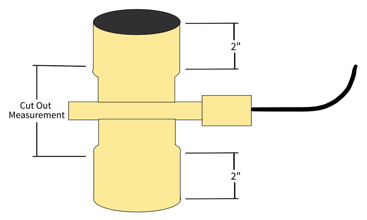
Locate a suitable place on your exhaust pipe to install the Sentinel Exhaust Brake. (Just after the down pipe is recommended.) Mark your exhaust pipe and cut out exhaust pipe section. (Grind or file the ends of the cut pipe so the Sentinel Exhaust Brake will slide on easily.)
Slide the Sentinel Exhaust Brake into the cut-out section. (Ensure that your exhaust pipe on each end is fully slid into the Sentinel Exhaust Brake.)
Clamp or weld both ends of the Sentinel Exhaust Brake to the exhaust pipes. (If clamping, retorque clamps after exhaust system has been hot at least once.) Note: The Sentinel Exhaust Brake will NOT build optimal back pressure if exhaust leaks are present. Make sure clamps are tight and no leaks between the exhaust brake and the engine exist (welding is recommended if capable).
Connect jumper harness to brake connector and safely route jumper harness up the frame rail and across the firewall in the engine compartment. (Ensure that jumper harness will not burn or chafe on any components.)
Route the remaining jumper harness through the driver side firewall into the cab. (Usually, the jumper harness can be slipped through an existing harness grommet without too much hassle.)
Secure jumper harness with zip ties and shrink tube to ensure it does not come apart. (Ensure that jumper harness will not burn or chafe on any components.)
Connect main harness to jumper harness and shrink tube connectors.
Connect the red wire on main harness to a KEY-ON 12-volt power. IMPORTANT – Main harness must be connected to KEY-ON power not constant power! (KEY-ON power is a circuit that has 12V power when the key is on and does not have any power when the key is off)
Connect black wire on main harness to a solid chassis ground.
Drill a 13/16 or 20mm hole in dash for switch. (Make sure the switch will be located in an accessible location.)
Remove switch from harness, remove switch mounting nut and install the switch using the nut. (Make sure the switch nut is snugged tight- Do not over tighten.) NOTE: The switch wires can easily be disconnected from switch by pressing the side tab on the connectors. DO NOT tug or forcibly pull the wires off of the switch.
Reconnect the harness to the switch (make sure connector clips together).
Secure main harness and control box using zip ties. (Ensure the main harness will not rub or chafe on any other components.)
Connect the GREEN wire coming from the controller to the throttle pedal or throttle micro switch. IF YOU WISH TO INSTALL THE SENTINEL EXHUAST BRAKE FOR MANUAL USE ONLY, connect the green wire to ground. When the green wire is connected to ground the Sentinel Exhaust Brake will open and close only with the dash switch. Be sure to review our Accelerator Pedal (Green Wire) Installation Instructions below. Installing throttle automation is recommended (rather than manual operation) to ensure the longevity of the exhaust brake and to prevent potential warranty issues.
Calibration - Start engine, with engine at idle, CYCLE THE DASH SWITCH ON AND OFF 6 TIMES WITHIN 6 SECONDS and wait 30 seconds. (Exhaust brake will not function properly without being calibrated to your vehicle.)
TURN EXHAUST BRAKE OFF WHEN USING CRUISE CONTROL
Final Steps
Control Box & Harness
Secure control box and harness with zip ties.
Ensure harness does not rub or chafe.
Reconnect Battery
Restore power and check that the controller powers up with ignition ON. (Dash switch will illuminate when on and key on)
Calibration, Testing & Verification
Start engine, with engine at idle cycle the dash switch quickly 6 times and wait 30 seconds. (Exhaust brake will not function properly without being calibrated to your vehicle)
After calibration, with dash switch ON — braking should engage.
Test proper function by lightly pressing accelerator — brake should immediately disengage before RPMs rise, confirming proper automation.
Inspect for exhaust leaks and secure all wiring.
Note - If exhaust brake does not function properly, calibrate again by cycling the dash switch quickly 6 times at idle and waiting 30 seconds.
Operation Instructions
When going downhill or coming to a long stop, push the Sentinel Exhaust Brake button to the down position (the light should illuminate). This will close the valve, engaging the exhaust brake. (Note: The controller on the main harness will ensure the exhaust brake fully closes.)
To disengage the Sentinel Exhaust Brake System, push the button to the up position (the light should turn off). This will open the exhaust valve, disengaging the exhaust brake. (Note: The controller on the main harness will ensure the exhaust brake fully opens.)
For manual operation, push the button down when exhaust braking is desired and push the button up when exhaust braking is not desired or when you are accelerating the vehicle. DO NOT accelerate vehicle with exhaust brake on (button in down position and light illuminated).
For automatic operation, push the button to the down position and the exhaust brake will engage immediately. With the exhaust brake on (button in down position and light illuminated), the Sentinel Exhaust Brake will disengage automatically when you press the throttle pedal, allowing you to leave the exhaust brake switch on while the vehicle in accelerating. IMPORTANT: Automatic operation works ONLY if the exhaust brake is wired into the throttle pedal, if it is not, DO NOT accelerate with exhaust brake on (button in down position and light illuminated).
When exhaust braking is no longer desired, push the switch off (light will turn off). This will open the valve and disengage the exhaust brake.
With automatic transmissions the Sentinel Exhaust Brake performs optimally ONLY in Tow/Haul mode. (Tow/Haul mode locks up the torque converter on your automatic transmission so down-shifting is similar to a manual transmission, causing your exhaust brake to slow you down using the powertrain.
TURN EXHAUST BRAKE OFF WHEN USING CRUISE CONTROL
Click the Installation Instructions below to download a PDF version you can print.
NOTICES
If you have an older vehicle with an automatic transmission and no Tow/Haul mode, you will need to install a torque convertor lock up harness to get the optimal performance out of any exhaust brake. To purchase the Sentinel Exhaust Brake Torque Converter Lock Up Harness go to the Bundy Motors Shop.
To become an affiliate and earn $100 per brake sold, .
For any other installation or operational question please , or call 435-704-2272.
Option A – Automatic Throttle Integration (Recommended)
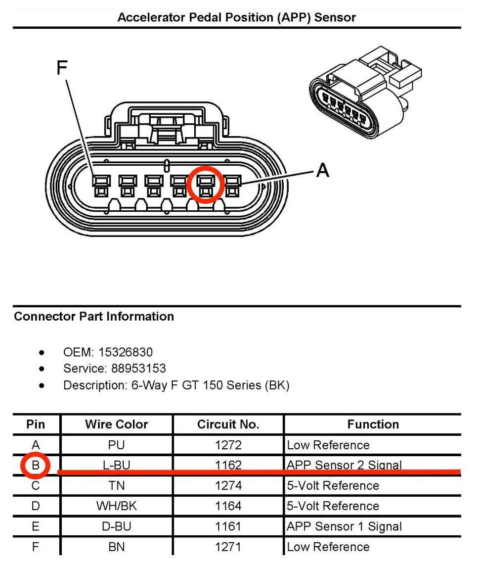
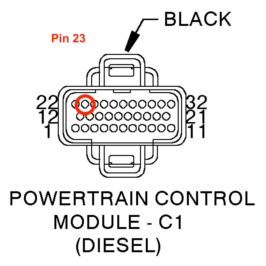
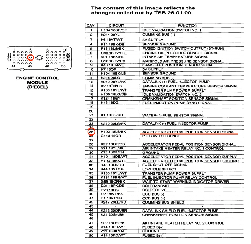
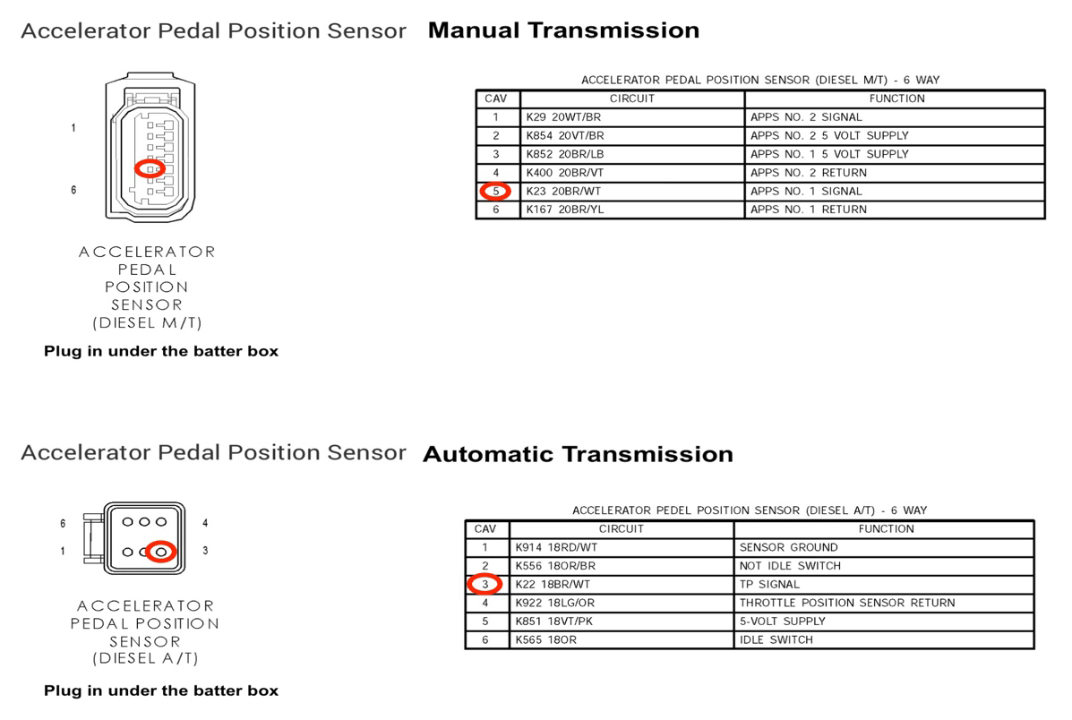
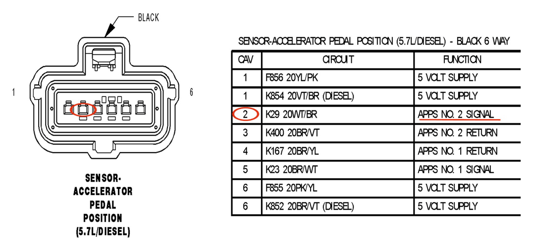
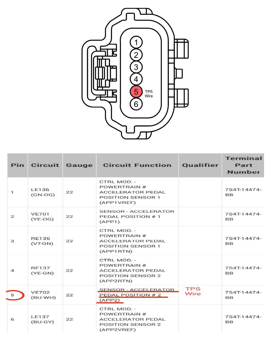
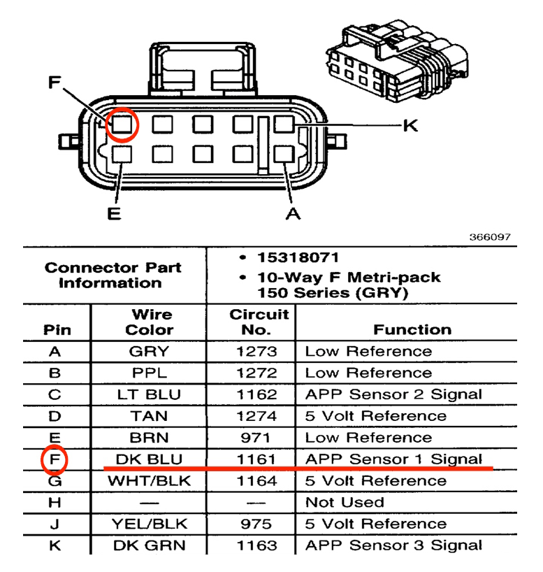
Identify the Accelerator Pedal Position Sensor (APPS) wire (see vehicle-specific diagrams).
Select a suitable spot on the APPS wire to tap into.
Using the black and red PosiTap: Unscrew the black side of the PosiTap and put the APPS wire in the slot, screw down the black side of the PosiTap. Remove approximately 1/8” of insulation on the end of the green wire, unscrew the red side of the PosiTap and insert the bear side of the green wire, tighten the red side down snug. This should create a solid secure connection between the green wire and the APPS wire.
How to locate the APPS wire:
This wire is on the accelerator pedal.
With the key on, the APPS wire has low voltage (under or just over 1V) and will increase voltage when pressing the accelerator pedal. (Increase should not go above 5V with the pedal fully pressed)
Some diagrams of APPS wire pins are below. If diagram is not below using a voltage meter to find the APPS wire. (Under or just over 1V and will increase voltage when pressing the accelerator pedal)
Option B – Manual Use Only (Not Recommended)
Connect the GREEN wire to ground.
In this setup, the brake will open and close only with the dash switch..
Note for Automating Mechanical Fuel Injection Systems:
Vehicles with a mechanical fuel pedal use a Microswitch to automate.
For automation, hook the GREEN wire to our microswitch on the fuel linkage.
IMPORTANT — Never hook the green wire to 12V power without OUR microswitch. This will damage the controller.
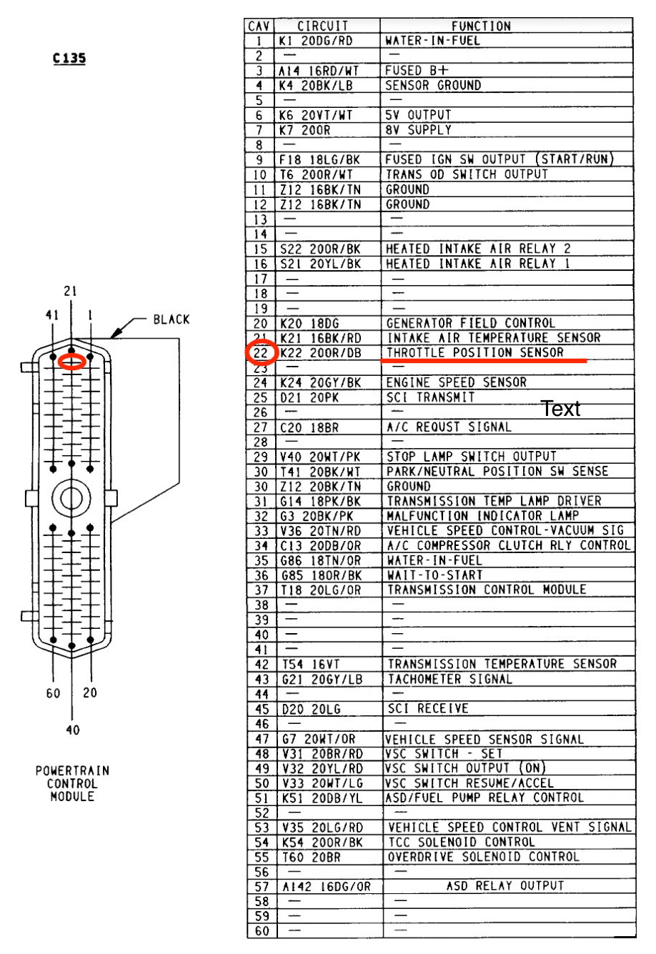
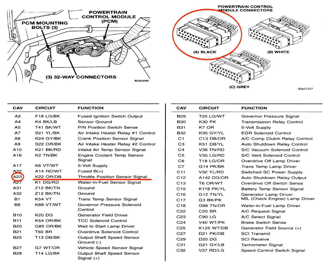
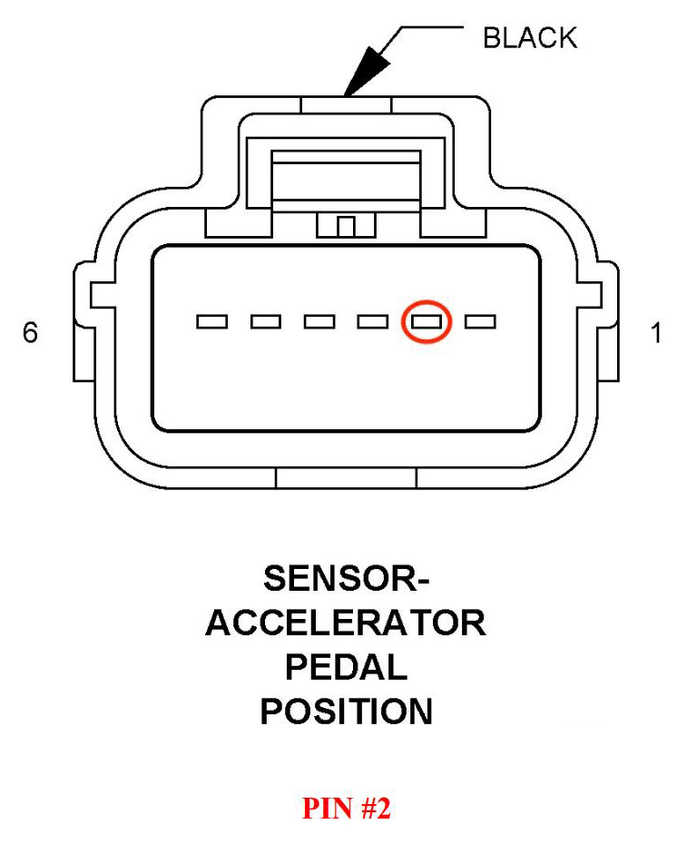
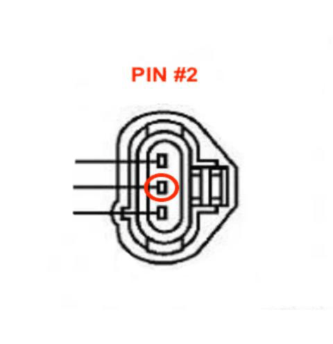
Accelerator Pedal Position (APP) Sensor Diagrams
DODGE / RAM
1994 –1995 5.9L Cummins
1996–2002 5.9L Cummins
1999-2002 5.9L Cummins
2003–2005 5.9L Cummins
2005-2006 5.9L Cummins
2007-2008 5.9L Cummins
2007-2024 6.7L Cummins
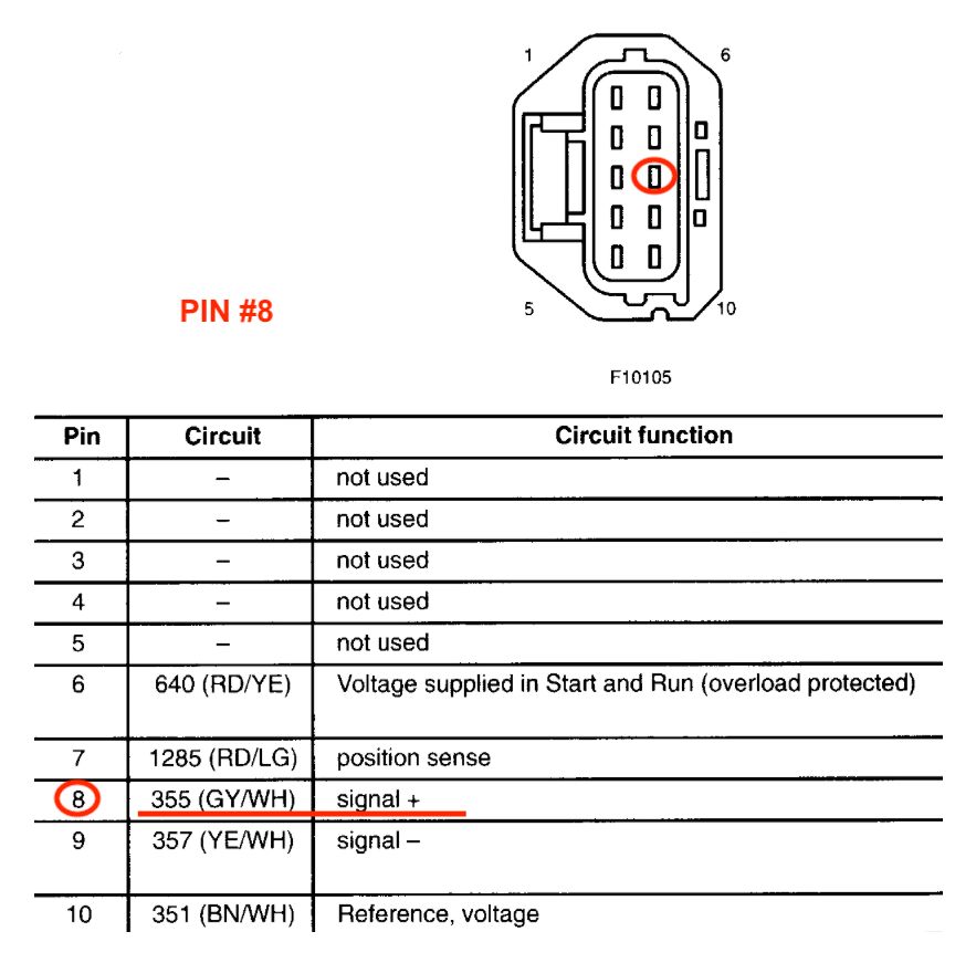
FORD
1995-2001 7.3L
2001-2003 7.3L
2003-2010 6.0L & 6.4L
2011-2024 6.7L
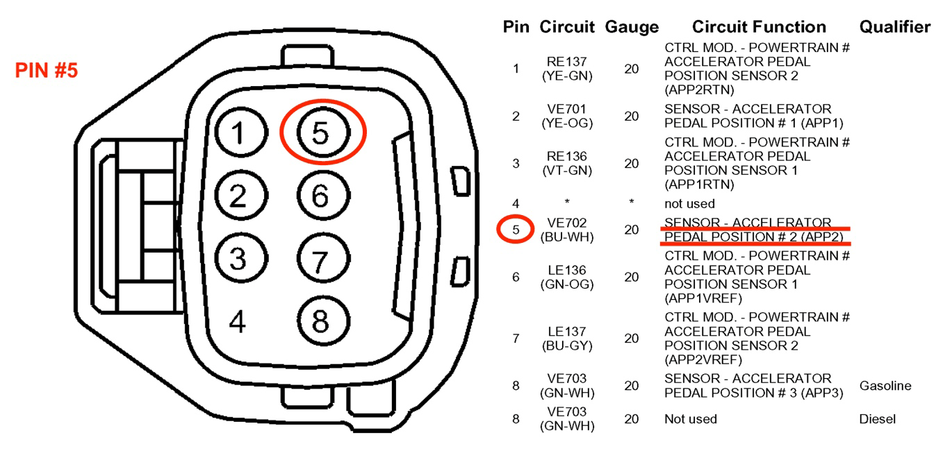
GMC / CHEVROLET
2001-2005 6.6L
2006-2021 6.6L